
Stylized rendering part the first: smoothed shading
In which Material Parameter Collections can be awkward, a box blur displays surprising capabilities, and a cartoon should probably be here, but isn’t.
Last time, I showed a NPR rendering test, and briefly mentioned the various systems that go into making it work. Now I’m examining the first of those systems, the screen-space shading smoothing that makes the shading look graphical.


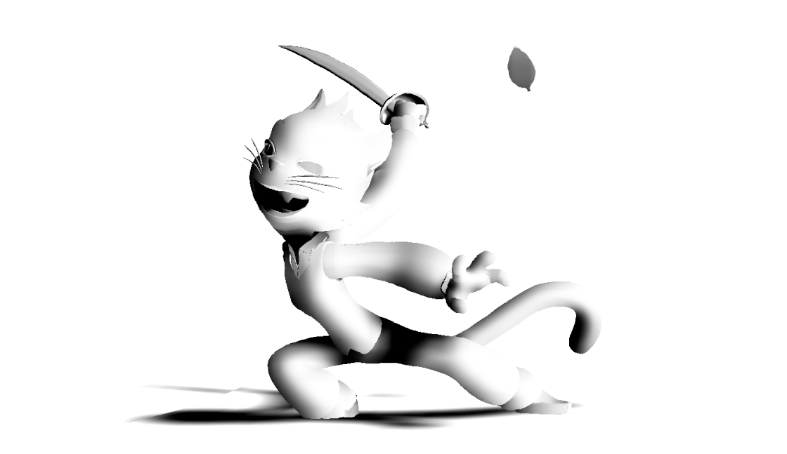
There are two techniques being used here. The first involves generating normals at render time for some spherical shapes. This is particularly useful on heads, where I really want to remove as much detail as possible. That doesn’t just go for facial features that are internal to the head shape--I also want her ears and hair tufts to change her silhouette but not add any internal detail to the shading. That’s an important part of making the head feel graphic.
This is very easy to do for any kind of spherical-ish shape. Basically, you just need to know what the center point of the sphere is. Knowing that is easy--I’ve constrained a null to her head in Maya and exported it to UE as an FBX.
Unfortunately, making that information available in a shader can be kind of awkward in UE. One way to do it would be to make the material a Dynamic Material Instance, so that a blueprint can set its parameter values at runtime. This works fine but requires some additional machinery to generate and keep track of the Dynamic Material Instance when needed, as you’d have a different one for each shot. Another is to use a Material Parameter Collection, which lets you set global values that any material can use. This makes it very easy to publish data--you just set a scalar or vector value, and any material can see it!--but since you’re limited to two Material Parameter Collections in any given shader, you basically have a limited number of namespaces which pretty quickly get cluttered with lots of different kinds of data you might want to publish. And either way, you have to actually make that data get published when needed.
In this case, I’ve chosen to use a value in a Material Parameter Collection, though I think a Dynamic Material Instance might actually be the right answer in the future, as I don’t care for how cluttered my Material Parameter Collections get. To publish that value, I made a simple Actor that gets it’s own location and sets the value in the Collection:

I’m calling the actor’s “Drive Head Point” blueprint from an event track in sequencer that triggers it every frame:

It’s kind of ugly but it’s easy to set up and it works. There are better solutions, but it looks like they’d require digging into the C++ side of UE more than I want to do right now.
Then, to create the normals, all the shader has to do is to create a vector using the position of the pixel currently being rendered and the spherical center point. And that’s all you need to do to make spherical normals! I’ve also added a texture map that lets me blend from the spherical normals to the vertex normals, so that I can tell some areas of the mesh, like the inside of the ears, not to use them.

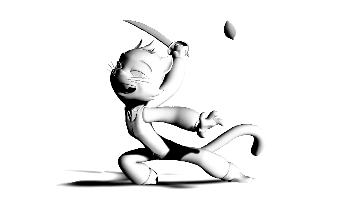
So that simplifies the head considerably, making the ears and hair tufts feel a lot more graphical. But it’s not sufficient, because the way the light reacts to the normals still feels like a 3D object--just a simpler object.
I don’t want the way light falls off to feel 3D. And of course, the rest of her body won’t be amenable to this technique; there’s no useful spherical center point for a hand or arm. You could do something more complex, like publish the control points of a spline that runs through the arm instead, and then find the closest point on the spline in the shader to give you a point to generate a normal from, but this presents both a bunch of additional problems (like, what if you have a mesh like the pants that would require multiple curves? Do you need weight values too?), is a lot more difficult to implement, and wouldn’t really solve the larger problem of “this shouldn’t even look like 3D falloff to begin with.”
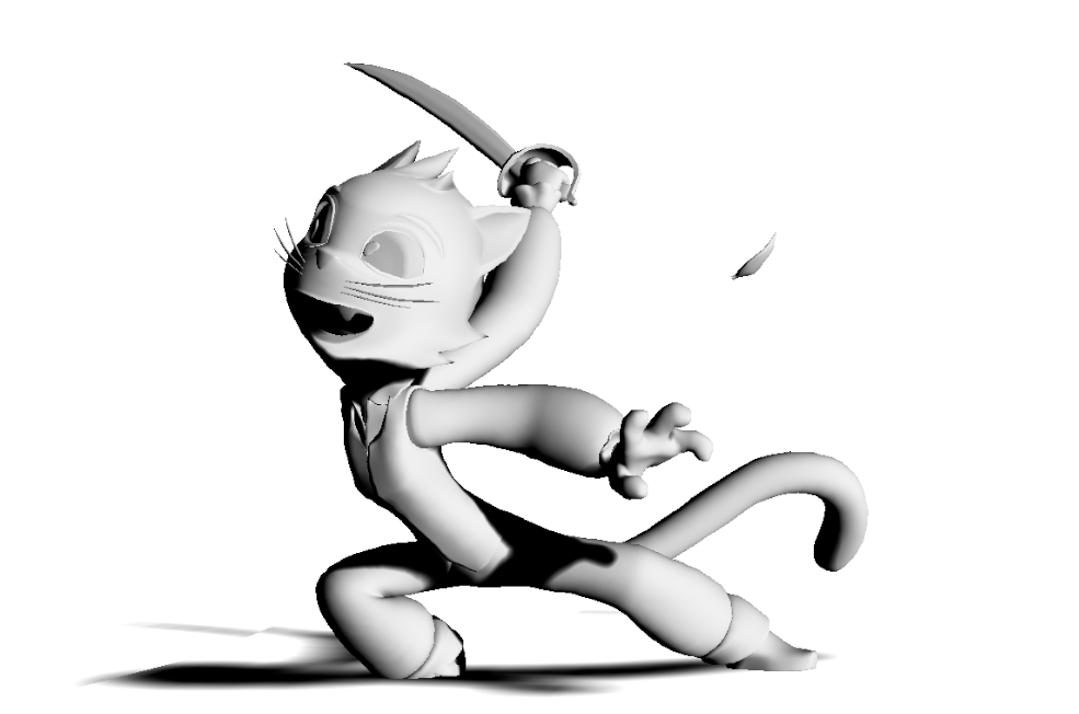
What I need is a general-purpose way of smoothing out shading. After years of trying out different techniques on different projects, I came to the conclusion that this really needed to happen in screen space. The problem with anything you do with 3D surfaces is that they look 3D. To make something graphical, you need to consider its shape on screen instead.
The solution I came up with is actually just a plain old box blur....but with some special additions. Just blurring the whole image would obviously be wrong. There are smart blur algorithms that try to smooth things in the image without removing visible details, but I specifically want to remove visible details! So doing a smart blur based on depth (for instance) wouldn’t work. Instead, I ended up solving the issue by specifically defining “blur regions.” I worked with Morgan Robinson to test this idea with a simple Python script, treating test images as Numpy arrays. Once the concept had been proven to work, I worked with Zurab Abelashvili to write an HLSL version that could be inserted into a UE post-process shader.
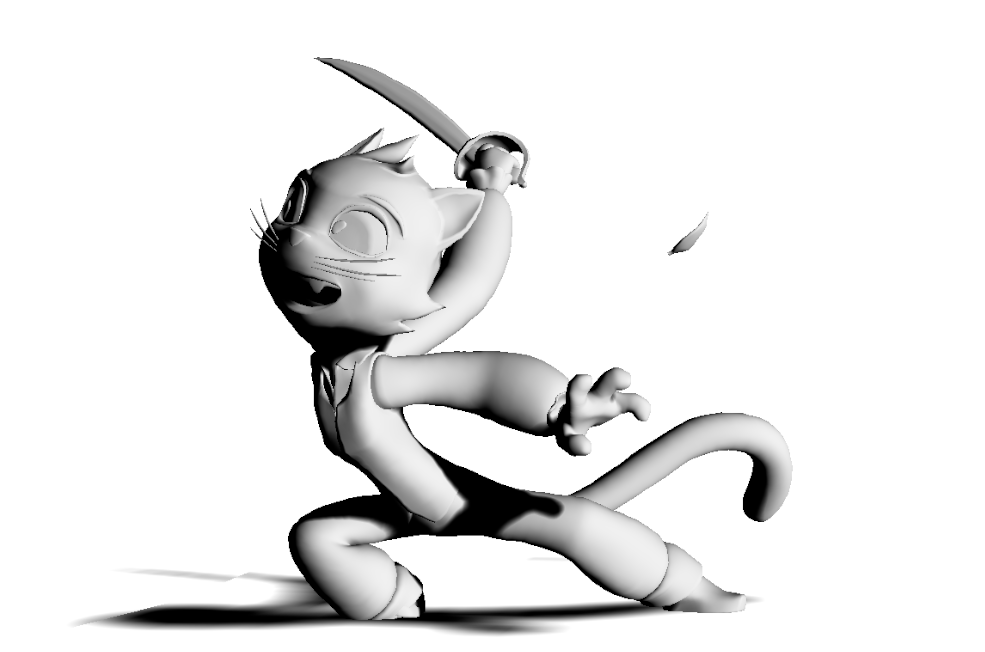
The way any blur works is that it looks at pixel values within a given window and averages them. You can cause the blur to happen within a specific region by simply ignoring pixels outside the region, and not including them in the average. For instance, if you blur the lighting pass and include only pixels inside the character’s shape, you get this:

The next step is to limit the blur to multiple specific regions. If the lower arm is in a different region from the upper arm, they won’t be able to blur together like this, even when the arm is bent. Implementing this with multiple masks and blur passes would be too slow, so I made a pass with color IDs instead:

While calculating the blur, you check each pixel that might contribute to the average, and ask whether it has the same ID as the pixel currently being rendered. If the answer is no, you ignore it. That gets you this:

Closer, but all the seams are a problem, and you can’t get around the need to have so many regions--if the upper and lower arms aren’t separate you'd get them blending into each other when the arm bends.
This can be solved by using secondary regions. So anything right at the elbow can blend with both the upper arm and lower arm, but the upper and lower arms can’t blend with each other. Put in a more strictly logical (and code friendly!) way, that means a pixel must be in both the same primary region and the same secondary region as the pixel currently being rendered to contribute to the blur.
Here’s our secondary regions:

You don’t need to have secondary regions everywhere—pixels that are black effectively mean that the pixel is part of the default secondary region, which means that only the primary regions will effect what pixels are considered, just as if there were no secondary regions. You only need to introduce them at the border between two primary regions to make it possible to blend over the border.
Here’s the result:

Mostly this has solved the issue, but smaller regions like the fingers are still showing banding. That’s because the radius of the blur is the same everywhere, which means it’s huge compared to the fingers. In order to avoid banding, the radius can’t be much larger than the size of the secondary regions in screen space.
Fixing that is just a matter of having a pass where each pixel is a multiplier for the radius value:

In this case the values happen to be flat across major sections of the character, because that’s all that was necessary here, but you could paint gradients that gradually shift the radius too.
To avoid rendering an additional three whole passes per frame, I combine the ID passes into a single render pass by sticking the primary IDs into R, the secondary into G, and the radius multiplier into B. This pass includes all the data needed to calculate the blur.

And the result of the blur using the data from this image looks like this:

That’s the result I’m using in the final render. There’s still a little bit of banding on the fingers. This could be removed by painting a map that lowered the radius for the fingers a bit more while keeping it what it is on the palm. However, this was never actually that noticeable once the blurred lighting pass was combined with color and rim passes, so I just left it in.
The post-process shader that performs the blur looks like this:

The blur is all happening in the custom node, with HLSL code displayed on the left. There are a few things going on here that I haven’t mentioned and aren’t specifically part of the blur process itself. The radius value is being made relative to the view size, so that I can change the resolution of the render and still get the same result. The radius is also being adjusted based on depth, so that the radius shrinks as the character gets farther from camera.
You may also note variables in the HLSL that refer to “OriginalNormal”—that’s left over from an earlier concept where I was planning to use this method to blur normal values rather then directly blur a lighting pass. In the future, we might get even better results using a Gaussian blur rather then a box blur, at the cost of increased complexity and decreased performance—since the radius is variable, we couldn’t just create a Gaussian matrix and reuse it for every pixel, we’d have to calculate the Gaussian weight values for each pixel independently, which isn’t generally something you want to do in real time with a large radius. There are probably ways to approximate a Gaussian blur that would be performant enough but I haven’t really looked into them. For the moment, the box blur seems to be working great.
Next time we’ll take a look at a good shadow extraction method for UE!